Author: John

  • FT-891 “Built in” Digi-Mode Radio

    FT-891 “Built in” Digi-Mode Radio

    I’ve had a Portable Zero Sprint battery case for the FT857D for several years now. I never found myself using it much as I tend to stay out and operate longer than any battery that would fit inside the case would allow. Consequently it has been sitting in a closet for quite some time and I was never sure what I would do with it.

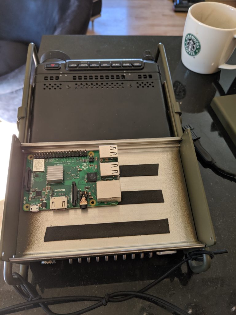
    Recently though, I moved the Escort rails to an FT891 and planned to use the 891 exclusively for digital in the field, I knew that I would use a Raspberry Pi as the digital interface but had just planned to put it into a case and bungee it to the top of the radio. Then one day while looking through the shack closet I saw the Portable Zero Sprint sitting there and had the idea to turn that case into a case for the Pi. This would allow a dedicated Pi to be hard mounted to the rig full time with very short cable runs to the back of the radio, thus building something as close to an all in one “Data” radio as possible without actually putting the Pi inside. (That is in the works for my Icom 7200) This modification would eliminate the vast majority of the setup time in the field!

    FT891 with the Escort and Sprint prior to build

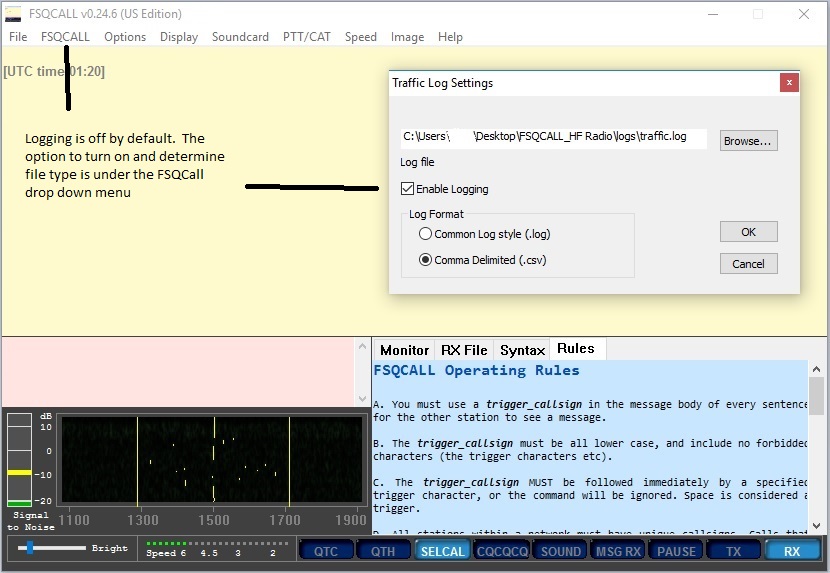
    So I immediately got to work mounting the Pi into the case, figuring out cabling and configuring an image on the SD card to support my field operations. Currently I’m ~ 99% JS8call since much of the time it’s the only thing working during this solar low we are experiencing. Therefore my overall Pi needs are relatively simple:

    • FLRig for Rig Control
    • JS8call
    • FLDigi
    • VNC for headless operation
    • GPS integration for both time and physical location
    • An accurate real time clock to maintain time between power ups
    • The ability to connect to wifi at home while also creating an adhoc wifi hotspot in the field

    FLRig was the obvious choice for rig control of the FT-891. When I first purchased the 891, the level of integration with FLRig was quite poor. So poor in fact that I put the FT-891 on the shelf and strongly considered selling it. At this point I am VERY glad I did not do that. The current version of FLRig has excellent support for the advanced features in the 891 and is at a level to which the operating capabilities are nearly identical to that of my primary station which is the Icom 7200, a Raspi and FLRig as the controller.

    The components used in this build are as follows:
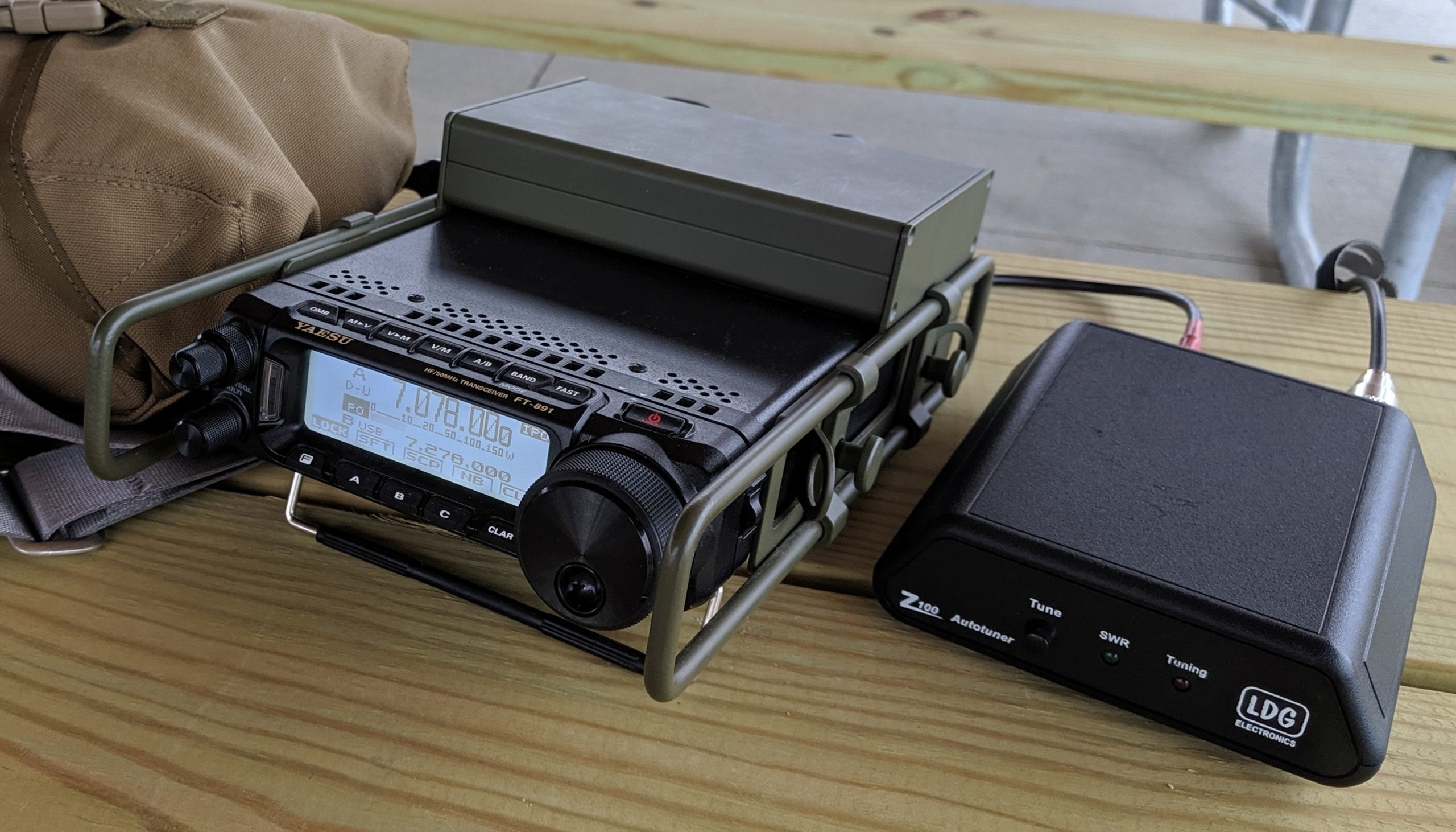
    Assembly:

    Pi mounted on standoffs

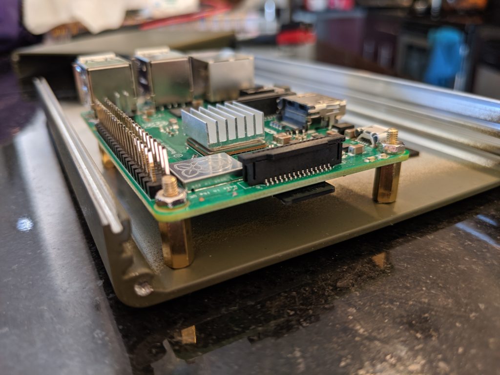
    Step 1 was to determine the orientation of the Pi in the case. It was not a particularly tight fit however I did have an overall height restriction to be aware of and also had to be aware of the overall length of the Pi plus anything plugged into the USB ports. It ended up with just enough clearance for everything but not very much extra.

    Positioning the Pi

    While I was figuring out the mounting I was also waiting for Amazon to deliver some cables. While waiting, I removed the plastic case from the Sabrent USB sound card I already had and also cut down the wires and removed the jacks from the ends of the computer to radio audio cable. Because of clearance inside the case I needed to remove the jacks and solder the wires directly to the sound card. After cutting the jacks I used my multimeter to determine which wire was connected to which portion of the TRS jack. Then I simply soldered the correct color wire to Tip, Ring and Sleeve portions of the sound card for both Mic in and Data out.

    Wires soldered to correct points on sound card

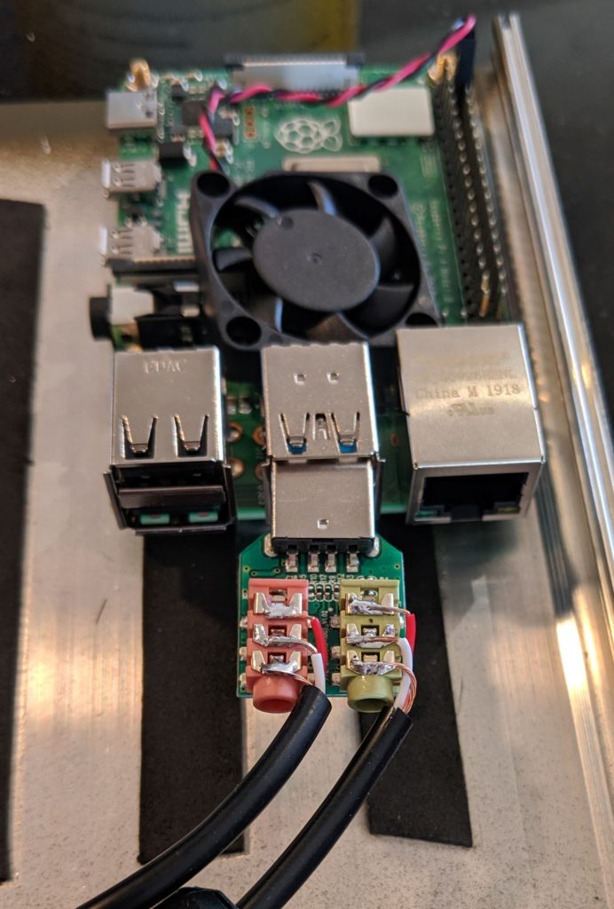
    These wires come labled “data in” and “data out”. These labels are from the “perspective” of the radio so be sure to connect “data out” to the mic input of the sound card and “data in” to the audio output of the sound card. Also, be sure to re-mark your wires below your cut line prior to making the cut so you do not need to later determine which wire is data in vs data out. I used some dots of red paint to designate the wire that went to the pink (mic in) connector.

    Once the cables arrived, the build went pretty quickly. I had some clamp on ferrites laying around and since everything is in such close proximity I figured they couldn’t hurt. Not sure if they were needed or not.

    Sound Card, USB for Cat Control and USB Extension for GPS all installed

    The part of the build that I worried about the most was drilling the large cable pass through hole on the back of the case. This is because the case splits 50/50 top to bottom so my hole had to span the seam. To solve this I marked the exact location of the hole and then removed all components from the build and double wrapped the entire case in blue masking tape. This would ensure that the two halves of the case do not slip or shift in any way while drilling. Next I found two thin boards and put the case between the boards and then dropped the entire sandwich into my bench vice. Unfortunately I did not take any photos during this process.

    The hole needed to span each side of this seam

    I drilled a very small pilot hole exactly at the center of the cable exit hole, then drilled increasingly larger pilot holes, until reaching 1/4”. At this point I switched to a step bit from Harbor Freight to finish drilling the hole to it’s final dimension of 5/8”. I wanted the hole to be a bit oversized so that the cables were not forced into an unnatural bend when passing through the case. Once the hole was drilled I very carefully smoothed and rounded the inside edges of the hole using a Dremel tool and also some fine sand paper so that there wouldn’t be any chafing or cutting of the cables when carrying the rig in a backpack.

    Cables have plenty of room to avoid pinching and chafe

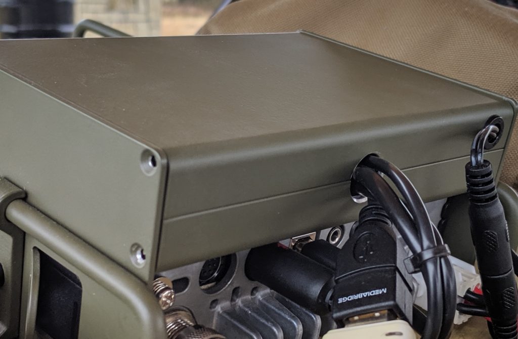
    Drilling the hole across the seam allows the case to open and close easily without having to worry about feeding cables through a hole in the case.

    Buck converter on lid with double faced Gorilla tape

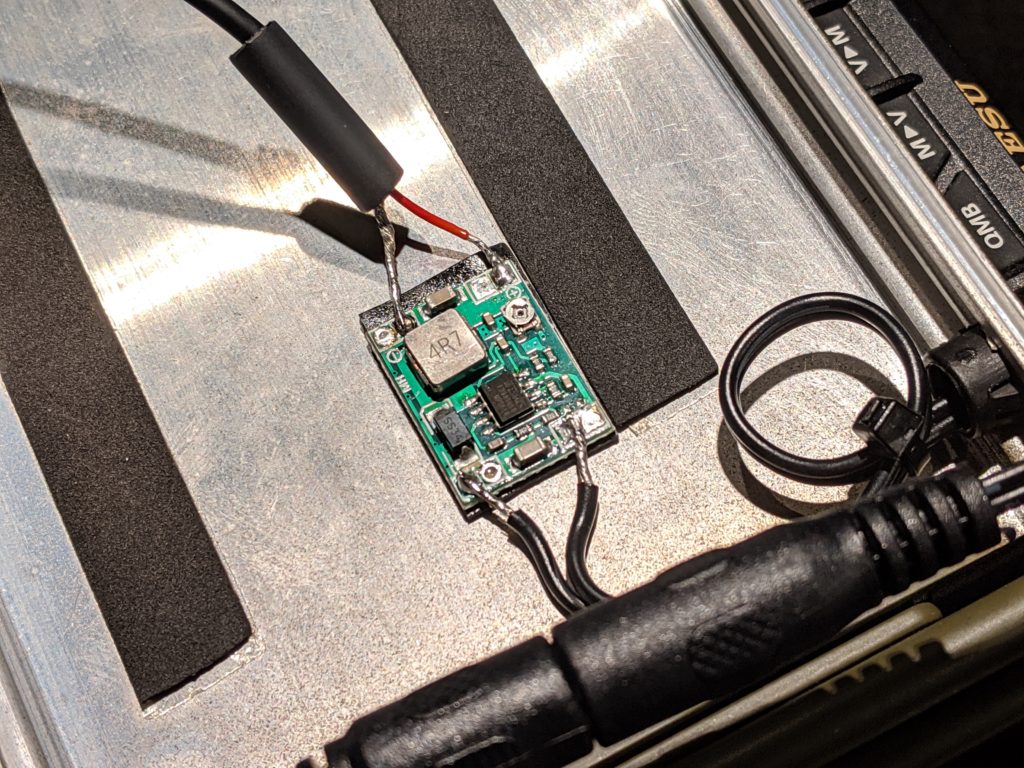
    Once this was complete, I installed the DC converter on the lid using Gorilla double faced tape and soldered the 5V USB C wire to the output and the 12v DC in to the input. Be sure to connect a small 5v fan or some other load to the buck converter to adjust the voltage output prior to connecting to the Pi. Apparently attempting to adjust these converters with no load can ruin the converter and obviously connecting it to the Pi without knowing it’s output voltage is putting the Pi at risk. Another option is to buy a fixed 5v output converter or UBEC. I liked this particular one because it is RF silent and very flat. There are UBEC converters that I have successfully used in other projects however.

    Complete kit for the first test

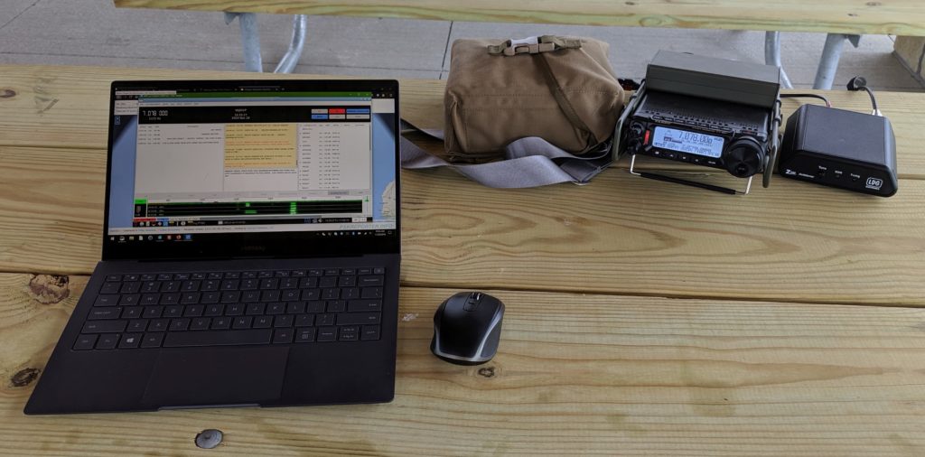
    There were still a few things to do but I was anxious to get it on air. The results were excellent and the setup time from the time I got out of the car to being on air was not much over five minutes. Plugged in the radio to the battery which powered on both the radio and the computer and booted up the laptop. While all that was starting I quickly installed the Chameleon hybrid micro with mil-ext, mil whip and ground spike, connected the coax to the tuner and the tuner to the rig and I was on the air.

    The real beauty of having a Pi dedicated to a specific rig is, once you get everything set up and working , it just continues to do so. There’s no configuring software, setting audio volume, etc.. just power up and go, everything is right where you left it last time.

    There are still a couple of things I would like to finalize / improve on this build. I converted the 5.5 x 2.1mm power pigtail coming out of the back of the computer case to a flush mount 5.5 x 2.1mm input however the ones I purchased seem to be junk and it’s easy to bump the cable and accidentally reboot the Pi so I’ll need a better input.

    Second, because of using a Pi4, passive cooling is a bit dicey. Probably fine in winter but would never work in a hot Kansas summer so it’ll be necessary to drill a grid of fan holes above the processor and mount a 40mm 12v dc Noctua fan inside the case. Noctua fans are the quietest and most durable fans available. They are not cheap Pi project fans. A Noctua fan is rated to run 24x7x365 for over seven years between failures. Once this is complete, I’d rather not have to open it up again very often.

    This step MIGHT be avoidable if choosing a Pi3B+ however one of my Pi3B+ machines will also get hot inside of a relatively sealed case so it may be required even for the 3B+, not really sure.

  • Using APRS Messenger with the Icom 7100 or 7200

    If you are reading this, you’ve no doubt discovered that APRS Messenger does not key the Icom 7100 or 7200 directly.   The APRS Messenger application does not send CAT commands for PTT and the Icom 7200 will ONLY take CAT commands for PTT when using the USB interface.

    To make this work, an additional piece of software is required. You can get that here:

    http://www.cantab.net/…/john…/Documents/CAT7200.html

    If you’re not an advanced Windows operator, this procedure will seem a bit challenging.  Take your time and follow all directions exactly and it will work fine.

    The new driver for the Virtual Com Port is unsigned, therefore you’ll have to bypass the Windows 10 security for installation of signed drivers. Here is where I found the instructions for this:

    https://www.lifewire.com/how-to-access-advanced-startup…

    I used method 2 from that article.

    When you reach the advanced startup options screen, follow the directions on this site to disable digitally signed drivers. Again I used method 2.

    https://www.howtogeek.com/…/how-to-disable-driver…/

    Once you’ve done that, go ahead and follow the directions for installation of CAT7200. Be sure to follow the additional instructions for Win7+ installation here:

    http://www.cantab.net/…/Documents/VCUSMInstallW7.htm

    Once it’s working, when the APRS Messenger app attempts to beacon, you will see the TX icon activate in the CAT7200 application as in the image below.

  • FSQ Tutorial

    FSQ (Fast Simple QSO) is a chat like, non-macro based, communication tool that allows for more a more natural conversation style. I have used this extensively on 80m NVIS, 40m NVIS and 2m for about a year with rigs running 24 x 7 out of my home in support of a local emcomm mesh. FSQ is based on MFSK and looks very much like Olivia in the waterfall.

    FSQ has some interesting advantages over other digital modes, primarily it is a “group oriented” mode meaning that it maintains a real-time contact list (chatroom type interface) as stations are heard in the waterfall. This happens automatically. As stations send their ID on a timed increment, each station who hears the ID will add that station to a “heard list”. Once a station is on the heard list you have several interaction options with that station.

    A few important things you can do are:

    • Query the location
    • Query your S/N ratio
    • Query their heard list
    • Relay messages to stations in their heard list that may not appear using that station as relay, replies from the other station will automatically be relayed back via the same path
    • Send messages to directly to individual stations or all stations
    • Transfer images

    FSQ is a standalone application and is my preferred interface however, FSQ is also integrated into FLDigi. For Linux users, I believe this is the only option currently. FLDigi works fine, early on I noticed that the standalone app had a higher success rate for decoding stations, this may have been addressed by now. One nice feature of the standalone application is the ability to run multiple instances simultaneously. This is how my station operates. I am able to run 40m during the day and 80m at night on HF and run 2m, 24×7 using the same PC for both rigs. I have never tried this with FLDigi.

    It’s designed to be used on a stationary frequency rather than tuning around the band. Because FSQ sits neatly in the center (1500) of the waterfall and occupies 400hz, it is easy to use FSQ to coordinate the sending of NBEMS forms in an adjacent slice of the waterfall using FLmsg.

    How to use FSQ:

    Here are the basics of how to use the FSQ Call application.  These screen shots were obtained using the US Edition of the FSQCall appliction.  There are newer versions, however the US Edition remains my preferred version.   FLDigi supports similar functionality, the user interface supports very similar features, it is just arranged a bit differently.


    General Tips

    The following are some tips that I’ve picked up while using FSQ:

    • use lower case as much as possible, the protocol works fastest and most accurately for lower case letters. do this everywhere possible, call sign, grid location, etc..
    • IMPORTANT!! Due to the built in relay features, The stations within a heard list make up a “mesh”. There are several ways to take advantage of this mesh.
      • Multi-hop relays are possible.
      • The response automatically returns via the same route that it was sent
      • Very strong stations with long heard lists can get beat up if overused
    • FLDdigi has a nice feature that allows you to put an expiration timer on stations in the heard list.  This is handy so that the heard list does not become artificially large.
    • Be sure to turn on logging. It is nice to go back and see which stations were in the heard list after a restart. You can repopulate the heard list quickly by typing “callsign?”. If that station is still in range, it will respond with your S/N and appear in the heard list.
    • Running both FSQCall and FLDigi/FLMsg simultaneously will allow you to maintain an FSQ Call conversation while simultaneously using adjacent portions of the waterfall for NBEMS traffic.
    • Automated Interactions with other stations are triggered using syntax that is appended after the callsign. I’ve included some of the ones I use frequently below.
    • The S/N ratio in the heard list next to each station tells you how reliably you are hearing that station. When a station sends a “?” to your station, that is the number they will get in return.    If you want to know how strongly another station is hearing you then the command is “callsign?”.
    • The remote station call sign is always followed immediately by the syntax character, no spaces.
    • Transmit speeds to not have to be syncronous. Each station can send at a speed that is optimized for the receive conditions of the distant operator.  FSQ-6 is perfectly compatible with FSQ-2.  This setting for your station can be controlled remotely by a distant operator.

    Syntax

    The FSQ syntax is simply a set of commands that the application will interpret and act on. The syntax characters are simply punctuation characters   ? $ @ & ^ _ * # + | ! ~ %   Each of these characters has a specified function that the FSQ application will take action on automatically.  I’ve included a few common examples below using my call as the “remote station”.  There are many others.

    n0jds?•  remote station would respond with YOUR S/N ratio as detected by the remote station.

    n0jds$•  This will direct the remote station to send back their entire heard list along with SNR. From here you can use this information to relay messages to stations that are not on your heard list but appear on theirs.

    n0jds<•  Directs the remote station to reduce its transmit speed by one step. n0jds>•  Directs the remote station to increase its transmit speed by one step.

    n0jds|some sort of text message or information•  This will put a pop up message on the screen of the remote station. When remote station reads the message, FSQ will automatically send an ack message back to the originating station.

    FLDigi Observations

    • Easy to switch between modes
    • Rig ControlFamiliar work space for many operators
    • Multi-platform support
    • Logging and QRZ Lookup
    • Expiration timer on stations in heard list

    FSQCall Observations

    • Unfortunately, it is Windows only currently.
    • All the rules, syntax, etc. are built into the program for easy reference.
    • I like to change the color of the waterfall when operating two radios simultaneously. I use a green waterfall on FM 2M and blue on HF. Very easy to know which rig I’m interfacing with. I have two copies of the application in separate directories so that all the config files for each rig are retained after restarts.
    • Dedicated interface makes it easier to use advanced features such as image or file transfer.


  • FLDIGI Tutorial: One click modem changes

    Here is the first FLDigi tutorial from a series that I am working on.

    I’ve added a second visible row of macro buttons above the basic set and I use that row to assign the modems I use the most. That way a modem switch from PSK-31 to Contestia 4/125 is one click of a button and not a hunt and drag exercise from the Op_modem list.

    First screen shot shows the second row of macro buttons. The way to enable a second row, go to Configure > User Interface> Macros. The one I’ve selected is “Two Scheme 4”.

    Clicking the button to the right of the macro row, with the number results in scrolling through rows 2 through 4 of the macro rows. I put my mode switches on row 3. You can put them on any row you choose.

    Now for the modes. Right click on an empty macro button or even on one that has a label. When you right click, you’ll have the option to edit. Remove all the existing text and the Macro Button Label information.

    Next, scroll down near the bottom of the “Select Tag” column and you will see a list of modems. Select the modem you want to create a macro button for, then click the green arrow button above to move it into the macro text window. Then, assign a macro button label. Hit “Apply” then “Close”. You’ll now have a very quick way to choose your favorite modes.

    One thing to note, for Olivia and Contestia, if you want to use the 4/125 that we have been using in the group you’ll have to add some additional info to the generic Contestia macro from the list. It should read <MODEM:CTSTIA:125:4>. You will have to add :125:4 to the text. Then apply and close.

    One additional issue I have discovered. If you set up an FSQ macro like I have here, you’ll have to use the Op_mode list to select a new mode to get out of it since macro buttons are disabled in FSQ.

    Enjoy your new “one click” freedom.